The VE.Bus BMS and VE.Bus BMS V2 are Battery Management Systems (BMS) designed to interface with and protect a single, or multiple Victron Lithium Battery 12,8V & 25,6V Smart (LiFePO4 or LFP) in systems that have Victron inverters or inverter/chargers with VE.Bus communication. It monitors and protects the batteries against over voltage and under voltage of any individual cell, and also over temperature or under temperature conditions.
Features
The next generation VE.Bus BMS V2
The VE.Bus BMS V2 is the next generation of the VE.Bus Battery Management System (BMS). It is designed to interface with and protect Victron Lithium Smart (LiFePO4) batteries in systems that have Victron inverters or inverter/chargers that have VE.Bus communication.
Protects each individual cell of a Victron Lithium Smart battery
For reliable and safe operation, a LiFePO4 battery must be monitored and protected against over voltage and under voltage of any individual cell, and also over temperature or under temperature conditions. The Victron Lithium Smart battery range includes integrated cell voltage monitoring, cell voltage balancing, and temperature monitoring. If the cell voltage or battery temperature is outside of the allowable range, this is communicated to the BMS via two BMS cables with M8 circular connectors. In systems with multiple batteries, the BMS cables of each battery are connected in series (daisy chained), with the first and the last BMS cables connected to the BMS.
Based on the status of the Victron Lithium Smart battery or batteries, the BMS will:
- Generate a pre-alarm signal to alert of an imminent cell under voltage condition.
- Disable inverting in VE.Bus inverters or inverter/chargers via VE.Bus, and disable other loads via the ‘Load Disconnect’ terminal in the event of a cell under voltage condition.
- Disable charging in VE.Bus inverters or inverter/chargers via VE.Bus, disable VE.Direct and VE.Can solar chargers via a GX device and disable other chargers via the ‘Charge Disconnect’ terminal in the event of a cell overvoltage, under temperature or over temperature condition.
Communication with VE.Bus products
MultiPlus, Quattro or Phoenix inverters connect to the MultiPlus/Quattro port with a standard RJ45 UTP cable. The BMS disables inverting in the case of a cell under voltage condition and disables charging in the case of a cell over voltage or temperature condition.
Communication with remote devices
A GX device (such as a Cerbo GX), Digital Multi Control (DMC) panel or a VE.Bus Smart dongle (including any combination) can be connected to the BMS via the ‘Remote panel’ port. These accessories can all be used in combination with the BMS to remotely control the VE.Bus Inverter or inverter/charger switch state (on/off/charger-only).
Auxiliary power input and output terminals
The BMS has a dedicated power output terminal (GX-Power) for a GX device and an auxiliary power input terminal (Aux-In) for an external DC power source, such as an AC/DC adaptor. In the event of a system shutdown, the GX device will remain powered via the auxiliary power input or be disconnected to prevent further battery discharge.
Remote terminals
These terminals can be used to switch the BMS on or off. When the BMS is off, both outputs will be free floating so that loads and chargers are turned off. There are two remote terminals, namely, Remote L and Remote H. A remote on/off switch or relay contact can be connected between L and H to switch the BMS on or off. Alternatively, terminal H can be switched to battery plus, or terminal L can be switched to battery Minus.
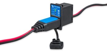
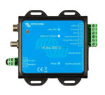
LED indicators
The BMS has the following LED indications:
- Status (blue): Lights shortly once every 10 seconds to indicate normal operation.
- Temp or Cell>4 V (red): Lights when the charge disconnect output is low because of cell overvoltage or overtemperature.
- Cell>2.8 V (blue): Lights when the load disconnect output is high and the battery cell voltages are above 2.8 V.
| GTIN | 8.72E+12 |
|---|---|
| Brand | Victron Energy |
| Manufacturer Part Number | BMS300200200 |
| Protection Category | IP20 |
| Dimensions | H24 x W95 x D106mm |
| Weight | 0.12Kg |
| Warranty | 5 Years |
| Country of Manufacture | India |